


© Website by Tooling Research Inc.

Whenever possible try to design long, thin parts around more readily available stock sizes to avoid having to machine long surfaces.
Machining material off of one face usually causes the material to distort or bow, so the machinist is often forced to remove material from opposing
sides equally to bring the material back into straightness. This is a time consuming requirement that often takes several operations to make the
material flat again. The full gamut of material selection cannot be covered in this article, but as a rule, larger cross sections of material that require
machining to thin profiles are going to distort at least somewhat.
When a machinist reviews your drawing he or she will be evaluating features, the steps it will take to produce that part with the least setups, and work
holding will be a major consideration. Whenever possible design your parts with at least two opposing parallel flat surfaces or a truly cylindrical surface
somewhere on the part so it can be gripped by conventional vises and tooling, otherwise custom fixturing or additional anchor material (extra material
to provide holding method) will be required, This raises cost of manufacturing significantly, especially on lower volume jobs.
The design itself;
By this time you have already decided what the function of your part will be, but very often you may not know what it will look like. Most designs evolve
around the function and how it will interact with other mating parts, so you will likely begin by choosing a basic shape, it will likely have holes, slots,
steps etc.
You could visualize the part as a blank of sufficiently sized raw material, then using your knowledge of basic machining practices begin to whittle away
the material of your model to create the contours. Or you could start by building up your features one on top of the other like building blocks. Either
way works. But t here are some things that you will want to consider.
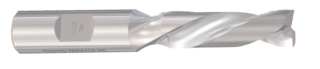
The tool length to diameter ratio is important;
Machine shops often receive drawings that require deep pockets with very small radii on internal corners, or worse yet no radius at all. Keep in mind
that milling is done with round tools called end mills, or milling cutters. These tools will be working for the most part on a plane perpendicular to the
feature face. As a rule the deeper the pocket, the larger the cutter diameter will have to be to create it. Smaller radii can be produced and even square
internal corners, but they require longer machining times, or alternate forms of machining such as broaching or EDM, which are both time consuming
and expensive. Keep in mind that a standard off the shelf end mill has a length to diameter ratio of 2 to 1. In other words the length will normally be
twice as long as the diameter. Although there are many cutters available that exceed this ratio there are reasons for maintaining this standard.
Small internal corner radius = small cutters = risk of tool breakage = longer machining time = higher costs.
Think like a machinist when creating solid models page 3
PAGE 1
PAGE 3


© Website by Tooling Research Inc.

Whenever possible try to design long, thin parts around
more readily available stock sizes to avoid having to
machine long surfaces.
Machining material off of one face usually causes the
material to distort or bow, so the machinist is often forced
to remove material from opposing sides equally to bring
the material back into straightness. This is a time
consuming requirement that often takes several operations
to make the material flat again. The full gamut of material
selection cannot be covered in this article, but as a rule,
larger cross sections of material that require machining to
thin profiles are going to distort at least somewhat.
When a machinist reviews your drawing he or she will be
evaluating features, the steps it will take to produce that
part with the least setups, and work holding will be a major
consideration. Whenever possible design your parts with at
least two opposing parallel flat surfaces or a truly cylindrical
surface somewhere on the part so it can be gripped by
conventional vises and tooling, otherwise custom fixturing
or additional anchor material (extra material to provide
holding method) will be required, This raises cost of
manufacturing significantly, especially on lower volume
jobs.
The design itself;
By this time you have already decided what the function of
your part will be, but very often you may not know what it
will look like. Most designs evolve around the function and
how it will interact with other mating parts, so you will likely
begin by choosing a basic shape, it will likely have holes,
slots, steps etc.
You could visualize the part as a blank of sufficiently sized
raw material, then using your knowledge of basic machining
practices begin to whittle away the material of your model
to create the contours. Or you could start by building up
your features one on top of the other like building blocks.
Either way works. But t here are some things that you will
want to consider.
The tool length to diameter ratio is important;
Machine shops often receive drawings that require deep
pockets with very small radii on internal corners, or worse
yet no radius at all. Keep in mind that milling is done with
round tools called end mills, or milling cutters. These tools
will be working for the most part on a plane perpendicular
to the feature face. As a rule the deeper the pocket, the
larger the cutter diameter will have to be to create it.
Smaller radii can be produced and even square internal
corners, but they require longer machining times, or
alternate forms of machining such as broaching or EDM,
which are both time consuming and expensive. Keep in
mind that a standard off the shelf end mill has a length to
diameter ratio of 2 to 1. In other words the length will
normally be twice as long as the diameter. Although there
are many cutters available that exceed this ratio there are
reasons for maintaining this standard.
Small internal corner radius = small cutters = risk of tool
breakage = longer machining time = higher costs.
Think like a machinist when creating solid models page 3
PAGE 3